
Metal Expansion Joint
- Keyser Metal Expansion Joints
- Applications For Axial Movement
- Applications For Lateral Deflection, Angular, Rotation And Combined Movement
- Material Evaluation For Hydro-Forming Process
- Types of Expansion Joints available
- Pressure Balanced Expansion Joints
- Elbow Or Tee Dual-Flex and Universal Series PBEU
- Cryogenic Application (Video)
In order to evaluate the loads upon piping, supports or equipment, the determination of the forces and movements required is essential in order to move an Expansion Joint. Due to this reason, the catalogs of most Expansion Joint manufacturers will contain force data to move a convolution to the rated axial movement established by the manufacturer. For convenience, it desirable to divide this force by the rated movement to obtain a bellows resistance factor or working spring rate, fw. in pounds per inch of movement per convolution. Once this factor has been determined, the movements and forces required to move an Expansion Joint may be calculated as follows: (Formulas from the EJMA Handbook Eighth Edition 2003 & Ninth Edition 2008)
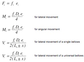
The preceding relationships are applicable in all Expansion Joints. It should be noted that every equation is dependent upon data which must be supplied by the Expansion Joint manufacturer. For standard designs, all necessary data is available in the catalogs of the individual manufacturer.
UNDER NO CIRCUMSTANCES SHOULD THE DATA OF ONE MANUFACTURER BE APPLIED TO THE PRODUCT OF ANOTHER DUE TO FUNDAMENTAL DESIGN DIFFERENCES.


Applications For Axial Movement
Diagram A
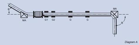
Diagram A displays the use of a single Expansion Joint to absorb axial pipe line expansion. One Expansion Joint is used between town main anchors (MA).
Diagram B
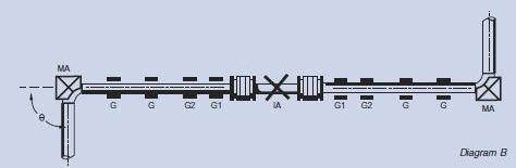
Diagram B displays the use of a double Expansion Joint to absorb axial pipe line expansion. There is a additional intermediate anchor (IA) dividing the pipe line into individual expanding sections with two main anchors, thus there is only one Expansion Joint between any two anchors.
Diagram C
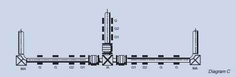
Diagram C displays the use of a Expansion Joints to absorb axial pipe line expansion in a pipe which a branch connection. The anchor at the junction (a tee) is a main anchor (MA) that is designed to absorb the thrust from the Expansion Joint in the branch line.
Diagram D
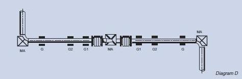
Diagram D displays the use of a Expansion Joints to absorb axial pipe line expansion in a pipe which a reducer. The anchor at the junction, which in this case is a tee, is a main anchor (MA) designed to absorb the thrust from the Expansion Joint in the branch line.
Diagram E
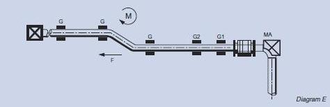
Diagram E displays the use of a single Expansion Joint to a pipe line containing an offset. Applications of this nature are not usually recommended. There will only be satisfactory performance within certain limits. At each ends, the line is provided with main anchors. This is to absorb the pressure, movement loading, and guide friction. Where the line contains an offset, this load must be transmitted through the offset leg, resulting in a moment on the piping. In cases where the line size is small, the offset appreciable, or where the pressure and movement forces are relatively high, this configuration may result in over stressing, or distortion of the piping and guides.
Diagram F
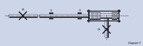
Diagram F displays the use of pressure balanced Expansion Joint to absorb axial line expansion. Take note that the Expansion Joint is located at the position where there is a change in direction of the piping, and that the elbow and the end of the pipe line are secured by intermediate anchors. A minimum of guiding is required since the pressure thrust is absorbed by the Expansion Joint itself, and only the forces required to deflect the Expansion Joint are imposed on the piping. Often, directional guiding adjacent to the Expansion Joint, as shown, may suffice. In cases where there are long, small-diameter pipe lines, additional guiding might be needed.
Diagram G

Diagram G displays the use of an in-line pressure balanced Expansion Joints to absorb axial pipe line movements in a long, straight piping run. With this arrangement, the two anchors shown are relieved of pressure loading and are designed as intermediate anchors. A minimum of guiding is requried in this arrangement, primarily to direct the thermal expansion of the piping into the Expansion Joints in an axial direction as the piping is relieved of compressive pressure loading.
Diagram H
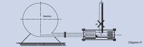
Diagram H displays the use of a pressure balanced Expansion Joint to absorb the thermal expansion of equipment such as turbines & compressors. The Expansion Joint is used primarily to minimize loading upon the equipment casing. Take note that only an intermediate anchor is required at the change of piping direction. However, no guiding is necessary if the Expansion Joint is located immediately adjacent to the machine.
Extra care & effort must be taken to provide sufficient flexibility in both the flow bellows and the balancing bellows to ensure that the forces required to compress the Expansion Joint do not exceed loading limits for the equipment as established by the equipment manufacturer.
Applications For Lateral Deflection, Angular, Rotation And Combined Movement
The selection and proper application of Expansion Joints for lateral deflection, angular rotation and combined movements is dependent on a number of considerations, which includes load limitations upon piping and equipment, the surrounding conditions, the piping configuration, the targeted cyclic life, and available supporting structure etc. There will also be cases where two or more types of Expansion Joints are required for a particular application. In this case, the selection then becomes purely an economic one. Often, one or the other of the available designs will carry certain unique characteristics which make it particularly suitable for a given application.
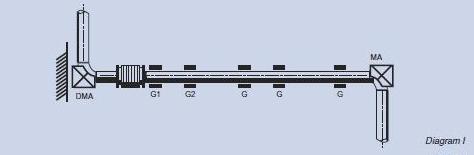
Single Expansion Joints
The Single Expansion Joint is considered first for any application mainly because of its low cost. Diagram I shows the application of a single Expansion Joint absorbing combined axial movement and lateral deflection. The system closely follows the arrangements shown for axial movement only in the preceding section. The Expansion Joint is located at one end of the long piping control and protection of the piping against buckling. The anchor at the left end of the line is a directional main anchor (DMA). The anchor permits thermal expansion of the short piping leg to act upon the Expansion Joint as lateral deflection while it absorbs the main anchor loading in the direction of the Expansion Joint axis. The anchor at the end of the shorter piping leg is an intermediate anchor as this main anchor loading exists only in the piping segment containing the expansion joint.
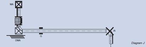
Diagram J displays an alternative arrangement where the Expansion Joint is installed in the short piping leg and the principal expansion is absorbed as lateral deflection. The longer the piping length is free of compressive pressure loading requires only an intermediate anchor and directional guiding. The functions of the directional main anchor and the pipe guide can combined in a single device.
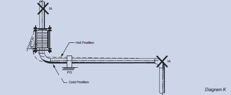
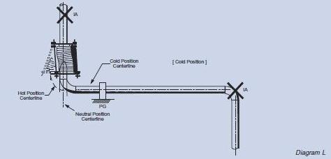
Diagram K & L illustrates modifications on Diagram J where the main anchors at either end of the Expansion Joint are replaced by tie rods. When applicable, the use of tie rods adjusted to prevent axial movement usually eases installation and lowers cost. However, because of these tie rods, the Expansion Joint is unable of absorbing any axial movement other than its own thermal expansion. As a result, the deflection of the piping in the shorter leg imposes deflection on the longer piping leg. In cases where the longer piping leg is not sufficiently flexible or where the shorter leg is dimensionally unsuitable, tie rods can be installed spanning the entire short leg to ensure no deflection is imposed.
Shortening of the Expansion Joint can result from the displacement of the tie rods when certain amounts of lateral deflection are imposed upon the Expansion Joints (as shown in Diagram K). Extra effort and care must be taken to ensure that sufficient piping flexibility exists to absorb this deflection of the piping. Minimizing the amount of this deflection is possible by cold springing the Expansion Joint in the lateral direction.
The limited amount of lateral deflection which such an Expansion Joint can absorb is the main restriction upon the use of single Expansion Joints for lateral deflection or combined axial movement and lateral deflection. The allowable lateral deflection is directly proportional to the ratio of convoluted length to diameter which, in turn, is restricted by considerations of stability and manufacturing limitations.
Universal Expansion Joints
The universal Expansion Joint is ideal for the absorption of lateral deflection. This design may also be used to absorb axial movement, angular rotation or any combination of the three. Using the universal Expansion Joint is its use as a tied Expansion Joint in a 90 degree piping offset with the tie rods adjusted to prevent external axial movement is one of the most typical application used.
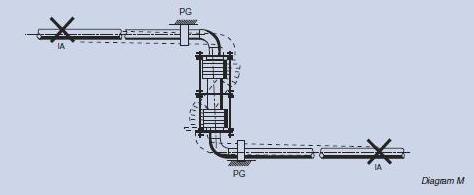
Diagram M illustrates a tied universal Expansion Joint being used to absorb lateral deflection in a single plane Z bend. Where dimensionally feasible, the Expansion Joint is designed to fill the entire offset leg to ensure that its expansion is absorbed within the tie rods as axial movement. The tie rod should also be extended to the elbow center line whenever practical. The thermal movement of the horizontal lines is absorbed as lateral deflection by the Expansion Joint.
Since the pressure loading is absorbed by the tie-rods, both anchors are considered intermediate anchors. As the compressive load on the pipe consists only of the force necessary to deflect the Expansion Joint, only directional guiding is needed. Any thermal expansion of the offset leg external to the tie-rods, i.e. the elbows at either end, must be absorbed by bending of the horizontal pipe legs. Considerations must be taken in the design of the guides to allow for both this deflection and the reduced length of the Expansion Joint in its deflected position. For long universal Expansion Joints under high pressure particularly, additional allowance might be necessary to compensate for stretching of the tie rods under load. Consulting the Expansion Joint manufacturer for recommended minimum guide clearances is strongly advised.
Material Evaluation For Hydro-Forming Process
By Singapore Institute of Manufacturing Technology (Project Code: S08-F-09)
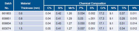
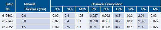
Keyser Technologies Pte. Ltd. developed the Hydro-forming process for the manufacturing of steam bellow components and has engaged SIMTech to evaluate the materials that could be used in this process. The materials that have been studied are stainless steel type 321, 316L and SUS304. The study aims to determine the flow stress data of these materials and to examine whether the influence of material direction is significant. Please note that while the test was conducted on 3 different stainless steel types, this report only includes the logarithmic plot of stress-strain data and tensile strength results of stainless steel type 316L (612663 0.6mm). Please contact Keyser Technologies for more detailed test results.
There are two main objectives in this study:
1) To determine the flow stress curves of the materials used for hydro-forming process from tensile testing.
2) To evaluate whether there is any significant influence of material direction on material properties.
Methodology
The materials evaluated for hydro-forming process are stainless steel Type 316L. Below is a summary
of the materials used in this study and their chemical composition.
Stainless Steel Type 321
Stainless Steel Type 316L
Stainless Steel SUS304

Types of Expansion Joints available
Control Rings
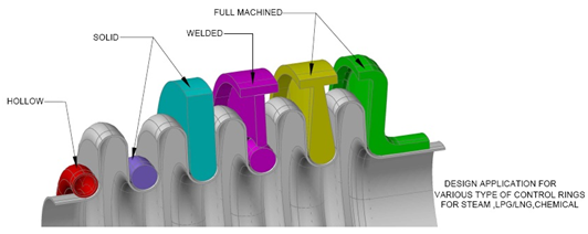
Features
Design application for various type of control rings for steam, LPG/LNG, chemical
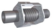
K-WA
Features
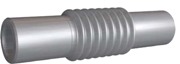
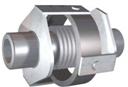
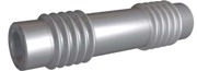
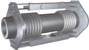
This Expansion Joint comprises of one single bellows accompanied with welding ends. While this model will absorbs all of the movements in any one length of piping, absorbing axial movements remains its primary role.
K-TE
Features
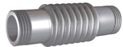
This model is similar to the K-WA model except that is fitted with BSP or NPT threads instead of welding ends. The threads are external.
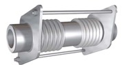
K-TI
Features
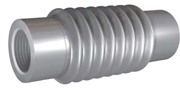
This model is similar to the K-WA model except that is fitted with BSP or NPT threads instead of welding ends. The threads are internal.
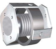
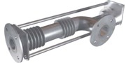
K-FA
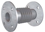
Features
This model comprises of a single bellows equipped with fixed flanges. While this model will absorbs all of the movements in any one length of piping, absorbing axial movements remains its primary role.
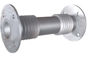
K-FF
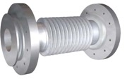
Features
This Expansion Joint is the same as K-FA except that it comes with floating flanges instead of fixed flanges.
K-WH
Features
Known as Hinged Expansion Joint with Welding Ends, this model comprises of a bellows fitted with welding ends and a system of articulated supports that allow Angular Movements in One Plane Only.
K-FH
Features
Known as Hinged Expansion Joint with Flanges, this model comprises of a bellow fitted with flanges and a system of articulated supports that allow Angular Movements in One Plane Only.
K-WG
Features
Known as Gimbal or Cardan Expansion Joint with Welding Ends, this model comprises of a bellow with welding ends together with two pairs of articulations linked up to a common floating ring. It absorbs Angular Movements in One Plane Only.
K-FG
Features
Known as Gimbal or Cardan Expansion Joint with Welding Ends, this model resembles K-WG except it comes with flanges instead of welding ends.
K-WL
Features
Known as Hinged Expansion Joint with Welding Ends, this model comprises of a bellows fitted with welding ends and a system of articulated supports that allow Angular Movements in One Plane Only.
K-FL
Features
The model resembles K-WL except that it comes with flanges.
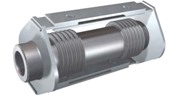
K-WD
Features
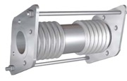
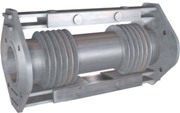
Known as Universal Expansion Joint with Welding Ends, this model comprises of two bellows joined together by a central pipe and fitted with welding joints. While this model can be used to absorb any combination of the three basic movements, absorbing lateral movements remains its primary role.
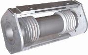
K-FD
Features
Known as Universal Expansion Joint with Flanges, this model comprises of two bellows joined together by a central pipe and fitted with flanges. While this model can be used to absorb any combination of the three basic movements, absorbing lateral movements remains its primary role.
K-WY
Features
Known as Hinged Expansion Joint with Welding Ends, this model comprises of a bellows fitted with welding ends and a system of articulated supports that allow Angular Movements in One Plane Only.
K-FY
Features
The model resembles K-WY except that it comes with flanges instead of welding ends.
K-WK
Features
This model is designed to absorb Lateral and Angular Movements in all directions. It is made up of two bellows joined together by a linking pipe and comes fitted with welding ends and a universal system of double articulated supports.
K-FK
Features
This model resembles K-WK except that it comes with flanges instead of welding ends.
K-PB
Features
Pressure Balanced – This Expansion Joint is specially designed for very specific situations. It is designed to absorb Lateral and/or Axial Movements Eliminating The Thrust caused by The Internal Pressure.
K-RW
Features
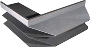
Camera Corner – Rectangular Expansion Joint With V-shaped Convolutions and Camera CORNER.
The applications of this model is exactly the same as the Circular Expansion Joints, and is characterised by the shape of its corner camera type and the V-shaped convolution. The connection elements are available with both flanges or welding ends.
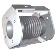
K-UX
Features
This Expansion Joint is used to absorb axial movements. Generally, it is made up of a single carbon steel or stainless steel convolution comprising of one thick ply. They are mainly used in heat exchanges etc.
K-RVV
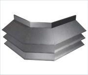
Features
Double Miter Corner
This is similar to the K-RV and the key characteristics of this model is by the shape of its miter type corner and its V-shaped or U-shaped convolution. The advantage of this is that the stress is more spread out resulting in a longer life cycle.
K-RV
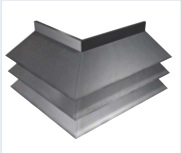
Features
Single Miter Corner – Rectangular Expansion Joint With V-shaped Or U-shaped Convolutions And Miter Corner.
The key characteristics of this model is by the shape of its miter type corner and its V-shaped or U-shaped convolution. The corner can be either single or double and the connection elements are available with both flanges or welding ends.
Pressure Balanced Expansion Joint
Keyser Pressure Balanced Expansion Joints are pressure balanced elbow or tee expansion joint systems specifically designed to overcome the reaction load caused by internal pressure acting, against turbine casings, pumps and other equipment. In situations where a main anchor cannot be installed to absorb axial and lateral motion, pressure balanced expansion joints are installed.
Keyser Pressure Balanced Expansion Joint design uses flow and balancing bellows inter-connected by using tie rods. The balancing bellows are subjected to the same line pressure as the flow bellows. When the flow bellow pressurizes, the tie rods extends the balancing bellows by an equal amount. There is no change in the volume, thus the pressure force remain in balance. Do note that there is no volume change when the flow bellows deflect laterally. The balancing bellows need only to contain the proper number of convolutions required to absorb the axial movements of the system. The axial force, however, is the total of the force required to move the line bellows and balancing bellows.
Key Features:
- Absorbs axial and lateral movements while restraining pressure thrust
- Eliminates main anchors
- Minimum guiding required
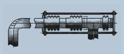
How Does Keyser’s Axial Pressure Balance Work
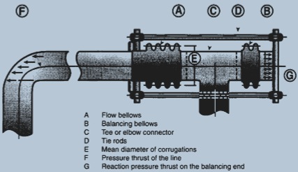
Internal pressure that have been built up causes a pressure thrust on flow bellows (A) and against the side outlet (elbow or tee) (C). This thrust is balanced by the identical internal pressure thrust (G) pushing on balancing bellows (B) that is transmitted back through the tie rods (D) counteracting the line pressure thrust (F). The force remaining is the axial spring force required to compress line bellows (A) and extend balancing bellows (B), plus whatever friction load is gnerated by the piping moving through the alignment guides.
Applications
Keyser Pressure Balanced Expansion Joints are used when there is a change in the direction of the pipe line, and most commonly used is adjacent to equipment such as pump or valves where allowable nozzle loads necessitate the elimination of pressure thrust.
Elbow Or Tee Dual-Flex and Universal Series PBEU
Keyser Pressure Balanced elbow model PBEU, functions on the same principle as the PBES model, with the exception that it has a universal flow bellow design. Commonly used when large amount of lateral movements are required or when the lateral force must be held to a minimum. In this design, two bellows are used in the flow end of the expansion joint and single bellows in the balancing end.
Pressure balanced joint has lateral pipe connection that can move easily between two bellows
The use of the connecting pipe from the elbow/tee for the balancing bellows must be large enough to assure rapid equalization of the pressure from balanced bellows with the pressure of the universal flow bellows.
Keyser PBEU series is used to absorb external lateral movement without impairing loading on the system when a pressure line that connects to a component is subjected to a large amount of lateral deflection. A universal bellow is placed at the flow end with a single bellow in the balancing end, joint by 4 tie rods. These tie rods pivot at their attachment joints. The lateral movements is taken by the flow bellow in the same manner as a tired universal expansion joint.Pressure balanced joint has lateral pipe connection that can move easily between two bellows.
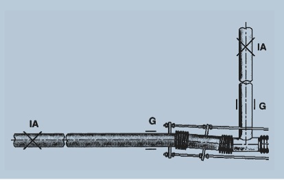
Guilding and anchoring construction in a Keyser PBEU universal pressure balanced expansion joint system
The diagram at the side shows a typical application of a pressure balanced expansion joint for combined axial movement and lateral deflection. The anchor on the piping run and that on the turbine are intermediate anchors and only directional guiding is required. By proper design, the guide directly above the turbine can be made to absorb the axial movement forces of the expansion joint without transmitting these to the turbine. The only force imposed on the turbine is that which is required to deflect the expansion joint laterally.